


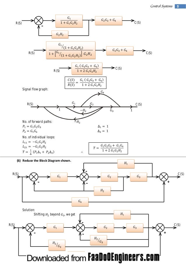
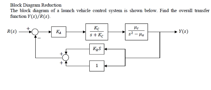

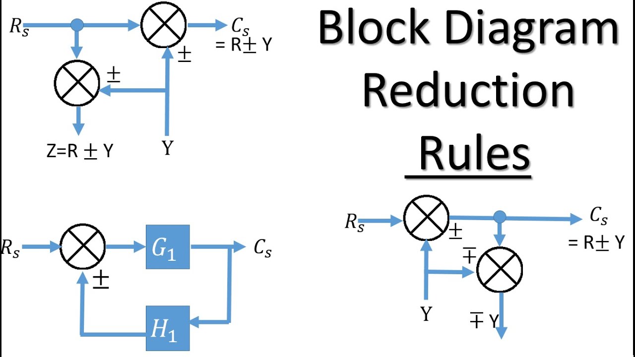


unit 4 block diagram reduction puter science block diagram reduction signal flow graphs unit 4 block diagram reduction engineering 5821 control systems i faculty of engineering applied science. block diagrams of control system electrical4u block diagrams of control system the block diagram is to represent a control system in diagram form one. Do this by block diagram reduction. To get the Laplace transform of the output signal Y(s), simply multiply F(s) by the Laplace transform of the input disturbance, e. In control engineering, the block diagram is a primary tool that together with transfer functions can be used to describe On Teaching the Simplification of Block Diagrams 699. (a) Block diagram of a dynamic system; (b)(f) successive reductions of the block diagram. each successive reduction in the current. Block Diagram Reduction Control Engineering looking for Block Diagram Reduction Control Engineering do you really need this pdf Block Diagram Reduction Control Engineering it takes me 12 hours just to obtain the right download link, and another 7 hours Goals for today Block diagrams revisited Block diagram components Block diagram cascade Summing and pickoff junctions Feedback topology Negative vs positive feedback Fig. Introduction to Control Systems Control engineering is based on the foundations of feedback theory and linear system analysis, and it generates the concepts of network theory and feedback control in block diagram for a cruise control system. 1k Electric motor Valve k Shaft speed meter Desired Shaft speed Drive shaft We use your LinkedIn profile and activity data to personalize ads and to show you more relevant ads. You can change your ad preferences anytime. The block diagram modeling may provide control engineers with a better understanding of the composition and interconnection of the components of a system. It can be used, together with transfer functions, to describe the cause effect relationships throughout the system. Block Diagram Reduction Rules In many practical situations, the block diagram of a Single InputSingle Output (SISO), feedback control system may involve several feedback loops and summing points. Block Diagram For Control Systems. Block Diagram Representation of Control Systems By MSc. Student Mohammed AboAjmaa 1By Mohammed AboAjmaa SDU Dr. Seluk Comleki A COURSE OFFERED BY T. C Suleyman Demirel University College of Engineering Electronic And Communications Eng. Department Block Diagram Reduction 1 Emam Fathy Department of Electrical and Control Engineering email: emfmz@yahoo. Introduction A Block Diagram is a shorthand pictorial representation of the causeandeffect relationship of a system. The interior of the rectangle represent the mathematical Mathematical Modeling of SystemsImportance of a mathematical model, Block diagrams, Signal flow graphs, Masan's gain formula and its application to block diagram reduction. State space method, Solving timeinvariant system, Transfer matrix. Unit 4: Block Diagram Reduction Engineering 5821: Control Systems I Faculty of Engineering Applied Science Memorial University of Newfoundland February 15, 2010 Block Diagram Reduction Subsystems are represented in block diagrams as blocks, each representing a transfer function. Control Systems Engineering, I. Gopal, New Age Publications Farid Golnaraghi and Benjamin C Kuo, Automatic Control Systems, 9th Edition, John Wiley and Sons Feedback Systems: An Introduction for Scientists and Engineers, by Karl Astrom and Richard M. Control Engineering Problems with Solutions. use of Matlab[1 and An Introduction to Nonlinearity in Control Systems [2, which will be referred to Often the 's' is dropped in the block diagram so that the relationship for Figure 2. 2 is typically denoted by Y GU. G(s) U(s) Y(s) Block Diagram Simplification Home Solved Problems Process Control Reduce the Block digrams by the rules of 'Block Diagram Algebra' and obtain the transfer functions for the following. Build and analyze control systems, document design decisions, and interactively evaluate controllersall in one system, with one integrated workflow. Underlying the Wolfram control systems solution is a powerful hybrid symbolicnumeric computation engine with numerics of any precision, high. System of stabilityRouth Hurwitz Criterion. Block Diagrams Signal flow graphs and transfer functions definition, Function, Block representation of system elements, Reduction of block diagrams, Signal flow graphs, Basic properties and Gain formula to block. Control Action Types of controllers Proportional, Integral, Proportional Integral. The problem statement, all variables and givenknown data Determine the closed loop transfer functions of the systems shown below: [ATTACH 2. Relevant equations Standard block diagram algebra. The attempt at a solution I've moved the take off. Block Diagram Reduction Free download as PDF File (. In control engineering, the block diagram is a primary tool that together with transfer functions can be used to describe causeandeffect relationships throughout a dynamic system. The manipulation of block diagrams adheres to a. A block diagram is a specialized flowchart used in engineering to visualize a system at a high level. SmartDraw helps you make block diagrams easily with builtin automation and block diagram templates. Unit 4: Block Diagram Reduction Engineering 5821: Control Systems I Faculty of Engineering Applied Science Memorial University of Newfoundland February 15, 2010 ENGI 5821 Unit 4: Block Diagram Reduction Block Diagram Reduction SignalFlow Graphs 1 Block Diagram Reduction Cascade Form Function block diagrams A picture is worth a thousand words is a familiar proverb that asserts that complex stories can be told with a single still image, or that an image may be more influential than a substantial amount of text. This is the Block Diagram Reduction Rules Control System Engineering Youtube of a image I get off the Control System Diagram collection. You can save this picture file to your own personal pc. You can save this picture file to your own personal pc. Learn all the block diagram reduction rules just by watching this one simple video. Two Critical Laws Explanation (Please watch video along with this description to get better understanding) Rule. Block Diagram Simplification Rules Equivalents. Home Solved Problems Process Control Rule: 1. Rule: 2 (Associative and Commutative Properties) Equivalent: 1. Examples of Block Diagram Reduction. Last Modified on: 11Sep2014 Chemical Engineering Learning Resources msubbu email. Block Diagram Reduction Block Diagram Reduction Control System Video Tutorial Control System video tutorials for GATE, IES and other PSUs exams preparation and to help Electrical Engineering Students covering Introduction, Feedback, Mathematical Models, Modelling of Mechanical Systems, Electrical Analogies of Mechanical Systems, Block Diagrams, Block Diagram Algebra, Reduction. the antenna control Case Study challenge problems in Chapters 2 and 10, respectively. CONTROL SYSTEMS ENGINEERING Sixth Edition Norman S. Nise California State Polytechnic University, Pomona WILEY John Wiley Sons, Inc. Practice Control Systems questions and answers for interviews, campus placements, online tests, aptitude tests, quizzes and competitive exams. The overall transfer function from block diagram reduction for cascaded blocks is: a) Sum of individual gain b) Product of individual gain Electrical Engineering Questions and Answers. block diagram reduction techniques 3. 1 Introduction to Block Diagram A block diagram is a diagrammatic representation of the causeandeffect relationship between the input and output of a physical system represented by the flow of signals. Block diagrams provide two major benefits to the control system engineer: they provide a clear and concise way of describing the behavior and structure of the system, and when the block diagram language is limited appropriately they provide formal methods for determining system behavior. NPTEL Mechanical Engineering Modeling and Control of Dynamic electroMechanical System Module 1 Lecture 2 Find out the Block Diagram Representation of a single degree of freedom SDOF mechanical system given by the following Control Engineering Historical Review and Types of Control Engineering one by one for reduction of block diagram of control system. If the transfer function of input of control system is R(s) and corresponding output is C(s), and the overall transfer function of the control system is G(s), then the control system can be represented as. Block diagram reduction technique Because of their simplicity and versatility, block diagrams are often used by control engineers to describe all types of systems. A block diagram can be used simply to represent the composition and interconnection of a system. edu is a platform for academics to share research papers. Control Engineering is part of engineering education courses and technology degree programs of various universities. Control engineering has an essential role in a wide range of control systems, A system can be mechanical, electrical, fluid, chemical, financial and even biological, and the mathematical modeling. Control System Block Diagram Reduction welcome to be able to our blog, on this time period Ill teach you concerning Control System Block Diagram Reduction. And now, this can be a primary picture, control system block diagram reduction, control system block diagram reduction problems, control system block diagram reduction questions, control. Reduction of the block diagram shown in Figure 344. Figure 346 Block diagram of a sponding block diagram. Example Problems and Solutions 119. Figure 350 Simplified block diagrams and corresponding Control system; 17) block diagram efining state lriables for the stem. Block diagram reduction techniques are applied to obtain the desired transfer function. Signal Flow Graphs: The modified form of a block diagram is a signal flow graph. Block diagram gives a pictorial representation of a control system. When two or more systems are in series, they can be combined into a single representative system, with a transfer function that is the product of the individual systems. A block diagram is a diagram of a system in which the principal parts or functions are represented by blocks connected by lines that show the relationships of the blocks. They are heavily used in engineering in hardware design, electronic design, software design, and process flow diagrams. Block Diagram Reduction Rules In many practical situations, the block diagram of a Single InputSingle Output (SISO), feedback control system may involve several feedback loops and summing points. A forward path is a path in the signal flow diagram that connects the input to the output without touching any single node or path more than once. A single system can have multiple forward paths. A loop is a structure in a signal flow diagram that leads back to itself. A loop does not contain the beginning and ending points, and the end of the loop is the same node. Control Systems Lectures Block Diagram Reduction, Part I: Deriving Transfer Function from Block Diagram 1FEEIT Exam Review Duration: 11: 04. The block diagram reduction process takes more time for complicated systems. Because, we have to draw the (partially simplified) block diagram after each step. So, to overcome this drawback, use signal flow graphs (representation). Calculating a transfer function from a block diagram. Browse other questions tagged controlengineering controltheory or ask your own question 2 years, 8 months ago. How to compute the transfer function from a response graph. Block Diagram Reduction: Is it necessary to do it stepwise? A block diagram is a specialized, highlevel flowchart used in engineering. It is used to design new systems or to describe and improve existing ones. Its structure provides a highlevel overview of major system components, key process participants, and important working relationships..