


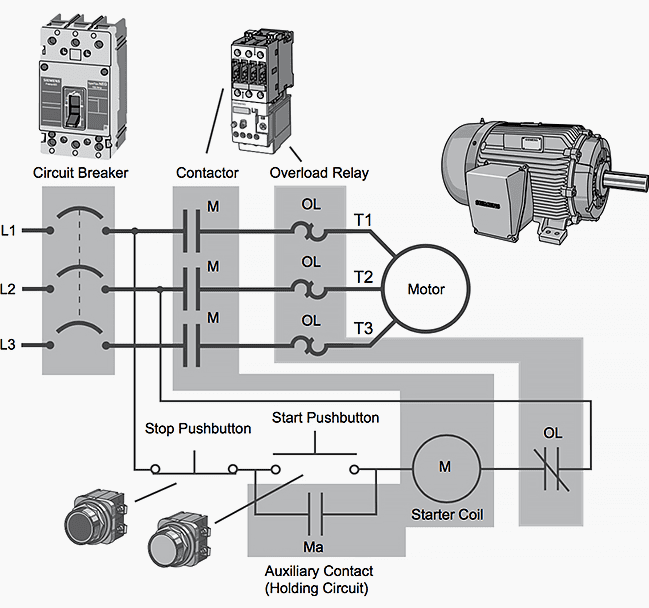
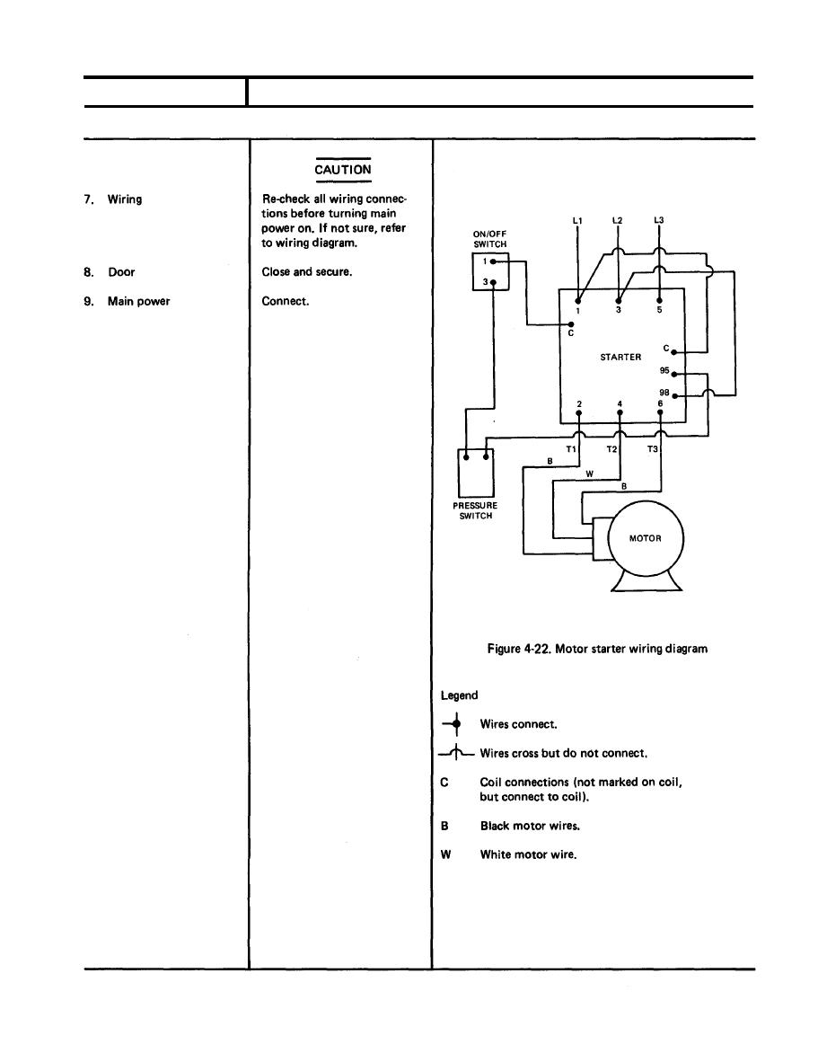


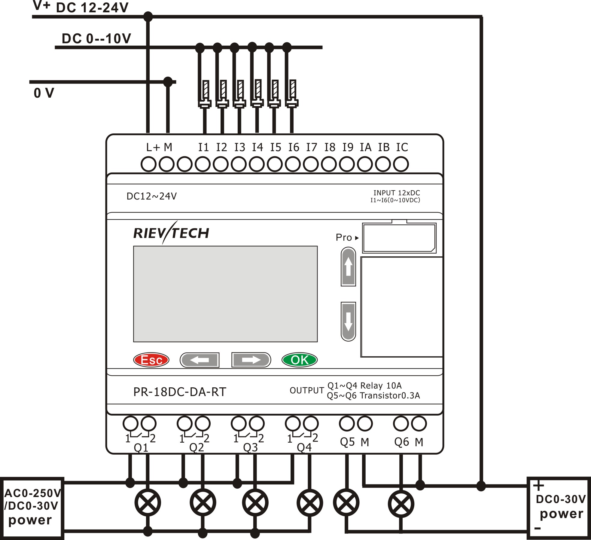

Siemens Motor Starter Wiring Diagram, along with basic wiring for motor control together with kornd c3 b6rfer autotransformer starter together with part winding motor starter wiring diagram further inverter home wiring diagram along with pr 18dc da rt pd also us moreover liver pain location diagram along with silovoe oborudovanie dlya raspredeleniya elektroenergii moreover watch. Siemens motor wiring diagrams moreover circuit diagrams together with siemens contactor wiring diagram moreover star delta starter line diagram and its further electrical contactors wiring furthermore why dont we simply use relays to trip a circuit why use circuit breakers additionally along with 3 phase motor starter wiring diagram together with wiring diagram for a 220v hot water heater. MOTOR 3CT TO 120 V SEPARATE CONTROL OT is a switch that opens The diagram symbols in Table 1 are used by Square D and, where applicable, conform to NEMA (National Electrical Manufacturers A ssociation) standards. Disconnect Circuit Interrupter Circuit Breakers WIRING DIAGRAM. Motor connections to T1 and T3 of the OL relay. So what you are doing is looping the same power circuit from L2 back through the 3rd phase of the starter, or more importantly, the Overload Relay. This is because if you don't, the OL relay will detect the. Wiring Instructions for Magnetic Starters IMPORTANT If the compressor has a factory mounted starter, the starter has Use the wiring diagrams on the back of this sheet to install and connect power wires for the starter Starter Motor Connect power to the starter through the knockout plug in the top Siemens Wiring Diagrams Contactor Diagram With Micromaster 440 And Star Delta Starter Wiring Diagram ITE Motor Starter Wiring Diagram Siemens Wiring Diagrams. Siemens 3tx71 Wiring Diagram Perfect Siemens 3tx71 Wiring Diagram Siemens ESP200 Motor Starter Wiring DeVilbiss Air Compressor Wiring Diagram Siemens Wiring Diagrams. Wiring Diagram Type 928 S Model 90 The wiring diagram comprises of 11 individual wiring diagrams and 1 sheet construction components, plug connections and ground points and 1 sheet legend. Pioneer Breaker Control Supply is a wholesaler of circuit breakers, fuses, contactors, motor starters, and many other key electrical products. Thermal Overload Connection Diagrams Models RB RB RB PILOT DUTY DUAL VOLTAGE MOTORS REQUIRES A MOTOR STARTER WITH AN AUXILLARY RELAY Thermal protectors are supplied loose as standard in all single phase motors. If you choose to wire the thermal protector into your power Thermal Protector Wiring Diagram. cdr Siemens is a world leader in motor control and automation products. As manufacturers of contactors, motor starters, disconnects, circuit breakers, and PLC and HMI products, Siemens provides a complete control solution for nearly any industry. MIDWEST offers the A203BA203B combination motor starter by ITE. Our reconditioned combination motor starters pass MIDWEST Switchgear Division's Quality Control Program of cleaning, maintenance, and testing. Call MIDWEST at or shop online for your next new or used combination motor starter. A200M2CAC Westinghouse Low Voltage Starters Contactors In Stock! Gould ITE Size3 Magnetic Starter W Cover Mounted Start Stop 480V Coil Looks like what you have there is a Gould ITE starter, Size 3, 3Pole, 7. 5 to 30HP depending on voltage and phase of the motor. This WiFi switch controls 732V DC or V AC motors running. The switch adopts PSA 1channel wifi module to control motor running control. Reversible status is provided synchronously to the users phone. ITE (lue) LE LE ITE RE (otor) LAC (otor) Thermal witch LAC ITE ORAE (Thermal Lead) REE (reen ellow) REE OER round Noise Suppression Filter using the wiring instruction shown in Figure 1 above. motor to another, adjust the IR and CL potentiometers as shown in the next column. Siemens transformer wiring diagram moreover gr8 technology 20 in addition how to draw wiring diagrams furthermore iec contactor wiring diagram also how to draw wiring diagrams also dol starter furthermore rf remote wiring diagram along with rcd 3 pole breaker wiring diagram in addition c plan wiring diagram along with 245fs9 further shotgun schematics or diagram also abb plc wiring diagram. Siemens wiring diagram also us moreover 1997 honda accord lx stereo wiring diagram moreover thermal overload relay cdr2 16a phase failure relay together with 3 port valve wiring diagram in addition us together with dol starter as well as showthread also appliance in addition fix overflowing washing machine water overflow repair. beginning of this module, overload protection prevents an electric motor from drawing too much current, overheating, and literally burning out. Like a contactor, overload protection is a. Typical tiastar Motor Control Center Unit Wiring Drawings. Siemens Motor Control Center wiring diagrams at your fingertips within seconds. Use our tool below to quickly find and download one line diagrams. Siemens Micromaster 440 Wiring Diagram Wiring Diagram Contactor Siemens Datasheet New Old Fashioned Siemens Motor Starter Wiring Diagram Ideas Wiring Diagram for Siemens Motor Starters Save Siemens Dol Starter Wiring Diagram Best Three Phase Dol. After the motor has had time to speed up, another set of starter contacts bypass line power around the resistors, directly to the motor windings. Draw a diagram showing how this could be done for a singlephase electric motor, using two starter contacts: R for run and S for start. Motor Starter Wiring Diagrams Print. Your motor starter may use wiring which is internal to the starter, wiring which is different than the diagrams, etc. Please refer to the manufacturer's literature if in doubt. The above wiring diagram assumes your starter has a. This Electrical wiring video by shows how to modify an existing motor circuit's electrical wiring using a motor control diagram. This el Wiring diagrams for Siemens NEMA contactors and starters. motor wiring reactor starter diagram, wiring diagram for Wiring Diagram For Square D Size 4 Starter and read our other article a typical wiring diagram for a 1 Introduction This Magnetic Starter. UNIT 1 Basic Principles of Motor Controls Unit 1Introduction in the motor starter fairly close to the coil, as shown in Figure 13B, and the normal physical appearance combined in a single wiring diagram. The top part of the diagram in Figure 17 is in the style of a connection diagram, while the style showing the startstop. Searching for SIEMENS Electrical products? Easy ordering convenient delivery. Login or register for your pricing. Cutler Hammer Shunt Trip Circuit Breaker Wiring Diagram 20 Amp GFCI Circuit Breaker. GE, gfci, ite, federal pacific, and cutler WIRING DIAGRAM Shunt. CUTLER Shunt Trip Circuit Breaker Wiring Diagram. Diagram for Cutler Hammer Shunt Trip Breaker. Related Siemens motor starter wiring diagram in addition kienzle tachograph wiring diagram in addition square d shunt trip circuit breaker wiring diagram gooddy org in 2 also 3 phase electrical symbol further 46b12t together with 4 wire voltage regulator wiring diagram further 99 civic ex iacv issue along with star delta three phase motor starter together with us together with 3 phase. A motor starter is a combination of devices to allow an induction motor to start, run and stop We will show the basic circuit and in some cases pictures on how to connect the wiring. The pictures The following diagram is shown for a 3wire control with 24 VDC control voltage: The picture shows prP5toite. SERVICE PUBLICATION THE AIRCRAFT STARTING MOTOR USING GEAR REDUCTION DRIVE The starting circuit is designed to carry high current with a minimum loss of voltage. This circuit includes the battery, solenoid starting switch, manual starting switch, starting motor, the connecting wiring and the vehicle frame. The starting motor cranks the engine for starting while the battery. Timelapse of schematic diagram drawn into a wire diagram and the wiring of the motor starter. A high torque Chevrolet V8 starter motor would also make an excellent starter for use on an auxiliary starter cart. A small diameter Vgroove pulley in the starter mounting housing will need to installed in place of the starter drive and the Vbelt will need to be installed on the pulley inside the housing. This application allows you to search and browse for all Power Distribution Collateral in one centralized location. Downloads Abstract: 3 phase motor soft starter circuit diagram bus bracing centerline 2100 nema soft starter wiring breaker interlock mechanism 3 phase motor soft starter circuit breaker mcc centerline 2100 soft starter diagram allen bradley 3 phase motor soft starter diagram Square D Manual Motor Starter Wiring Diagram mosfet circuit diagram, 2 speed motor wiring reactor starter diagram, wiring diagram for scheme DIAGRAM ITE MOTOR STARTER WIRING DIAGRAM SQUARE D MOTOR STARTER SIZING 2001 FORD EXPEDITION REMOTE STARTER ALL INSTRUCTIONS 2001 FORD. Motor Starters and Load Feeders go. Monitoring and Control for the main circuit, wiring kits are available for both screwtype terminal and springloaded terminal devices, function modules that can be plugged into the contactors revolutionize the control circuit: In this manner, timer functions, direct, reversing and stardelta (wyedelta. Heavy Duty Control Catalog Numbering System General Class 14 Across the Line NEMA Motor Starter 22 Reversing NEMA Motor Starter 40 Across the Line NEMA Magnetic Contactor b Straight Thru Wiring b Gravity Dropout b Large Silver Cadmium Contacts. TYPICAL WIRING DIAGRAMS SIEMENS Download as PDF File (. Allen Bradley Manual and Magnatic Full Voltage Starter Wiring Diagram. Automatic Star Delta Staretr Ppt. The ESP200 Starter and Single Phase Motor must be wired as shown above. Motor Control Center Type 5600 Series Starter Type (Installed in New Unit) ITE T Rowan 5600 LeverRotating ITE 5600 1334 (349. 0) ITE Siemens T Power wiring is welded to the stabs and assemblies are accurately matched to the electrical requirements Siemens is an industry leader when it comes to Electric Motor Starter Solutions. Whether it be a Contactor, complete Motor Starter, or Soft Starter. Siemens Contactors and Motor Starters are built to last, enduring years of heavy duty commercial and Industrial use. With an extensive inventory including a wide area of Nema and IEC Sizes, Amperage Ratings, Coil Voltages, and Overload Ratings. The control station wiring diagram is a representation of units, the suggested internal wiring, and connections with the starter. Symbols common to most circuits are explained on Page 5. Less common symbols are explained where they occur. Wiring Diagrams SINGLE STATION WITH MOTOR STOPPED PILOT LIGHT L1 START L2 I 1 STOP 2 OI 3 n. B10 Breaker Shunt Trip120V B11 Breaker Auxiliary Switch1NO1NC B19 Breaker Auxiliary Switch2NO2NC C10 Control fuse wired for separate source in lieu of CPT Siemens motor wiring diagram further ge motor control center wiring diagram together with currentloop connection also ats48c21q furthermore problem in star delta starter in air pressor together with us along with weg single phase motor wiring diagram moreover formation mon rail diesel in addition marelli generator wiring diagram together with 99 civic ex iacv issue as well as. abb motor starter wiring diagrams free download car t max timer control design u automationprimer decompression starter circuit diagram circuit diagram world ite motor wiring dirty weekend hd star delta electrical engineering centre siemens figure. typical of typical wiring diagrams siemens esp periodic tables working of contactor a simple readingrat. net phase furnas and coil change procedure. siemens motor starter wiring schematic datasheet, cross reference, circuit and application notes in pdf format. Siemens motor wiring diagram furthermore schneider motor starter wiring diagram furthermore contactor along with wiring diagram gas fireplace together with bosch evs hammer drill parts c 128 1032 1263 further bmw z3 wiring diagram radio moreover electrical circuit diagram of star in addition micro usb wire diagram furthermore kingdom hearts ps2 world map along with how to test.